
Dew point control for a battery enclosure should be defined around the coldest relevant surface and the moisture condition of the air touching it. The control specification must also state where the air is measured, how measurement uncertainty is handled, and which operating transitions are included. A universal setpoint or fixed temperature buffer cannot define a defensible control condition for every enclosure and event.
Key takeaways
- Start with the coldest relevant surface and the dew point of the nearby air.
- Document measurement location, range, calibration, response, and uncertainty.
- Evaluate shutdown, restart, door opening, and ambient transitions separately from steady state.
- Do not publish a universal dew-point target or fixed temperature buffer.
- Let the system designer own the integrated condition while the equipment manufacturer reviews a defined duty and interface.
The condensation condition
Condensation becomes possible when a surface is colder than the dew point of the nearby air. ASHRAE describes this condition and notes that conductive paths can create local cold spots, with actual minimum surface temperature best determined by testing (ASHRAE Handbook, Chapter 22).
This gives the project a defensible comparison:
- identify the surface that matters;
- determine its temperature during the event;
- determine the dew point of the nearby air at the same time;
- include measurement uncertainty and response behavior;
- decide what control response is required under project-defined risk criteria and assigned responsibilities.
The comparison is simple in principle but difficult in execution. Most errors come from using the wrong surface, the wrong air sample, or a steady-state reading for a transition event.
Identify the coldest relevant surface
The coldest surface is not always the outer wall or the point nearest the air conditioner. It depends on envelope construction, thermal bridges, air distribution, component mass, outdoor exposure, and equipment operation.
Review:
- door frames, panel joints, fasteners, and structural members;
- cable glands, busbar penetrations, and service openings;
- walls or roofs exposed to low ambient temperature;
- surfaces in direct contact with cool supply air;
- components that retain a low temperature after a cycle change;
- isolated cabinets or corners with weak air movement;
- drains, pipes, and other local thermal paths.
Use thermal review, event photographs, surface measurements, or testing to determine which point is credible. Do not declare a project cold point from a generic enclosure diagram.
The word relevant also matters. The project team must decide which surfaces and components are included in the control objective. An accessible wall panel, an internal electrical part, and a sealed sub-enclosure may require different observation and responsibility plans.
The primary task here is visible surface condensation: compare the measured or validated temperature of the protected surface with the dew point of nearby air at the same time. Moisture hidden within a layered wall or insulation assembly is a separate construction assessment; surface measurements alone cannot establish its internal condition.
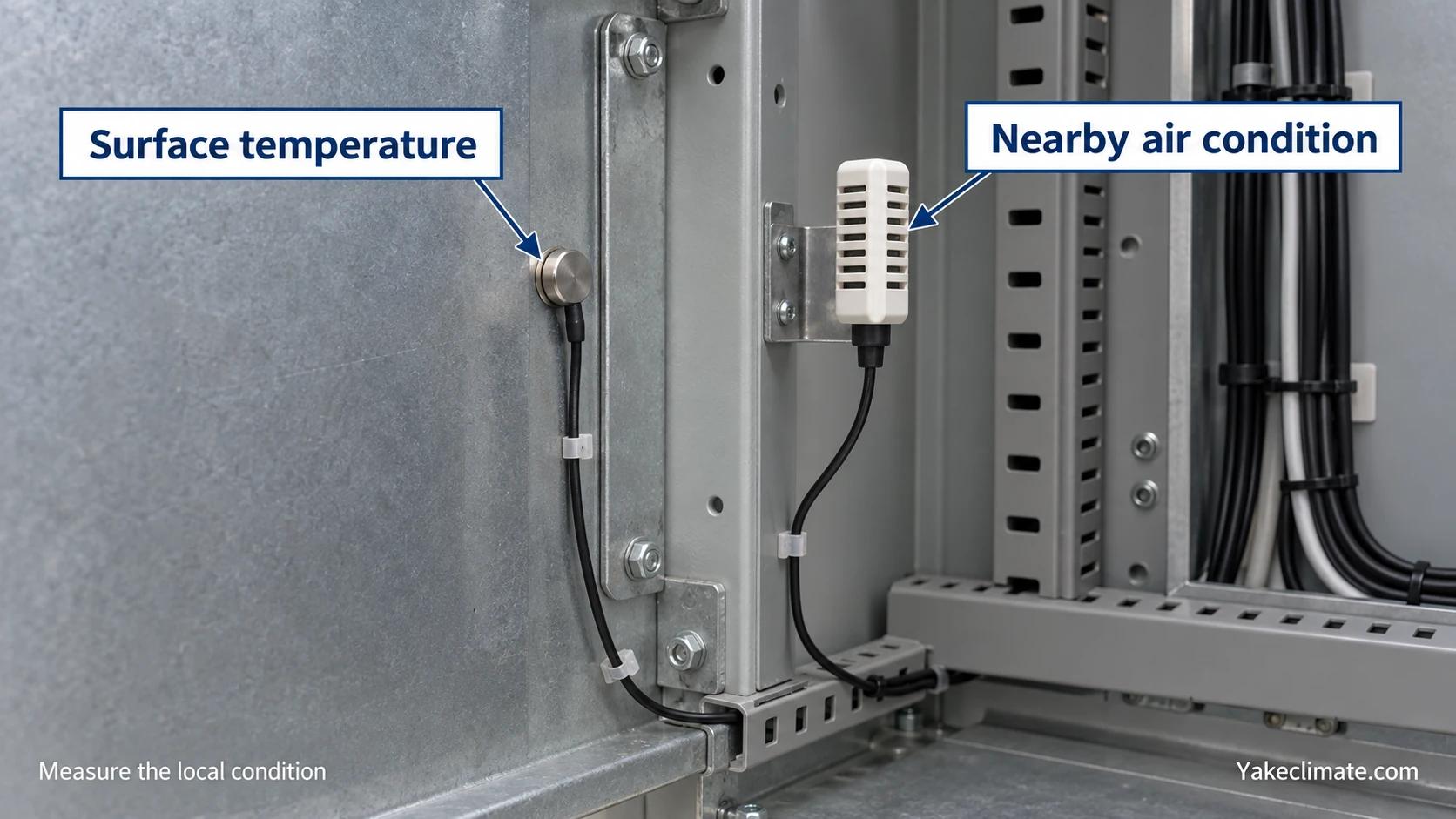
Measure the nearby air, not a convenient room average
Dew point expresses the moisture state of the air. The U.S. National Weather Service describes a chilled-mirror method in which a cooled surface reaches vapor-pressure equilibrium and condensation is detected, while also noting response and contamination effects (National Weather Service). This is useful measurement background, not a cabinet instrument specification.
For enclosure control, define the measurement boundary:
| Field | What must be stated | Why it matters |
|---|---|---|
| Quantity | Dew point, RH and temperature, or another project-defined quantity | Different quantities are not interchangeable without conditions |
| Air-sample location | Near the risk zone, return air, supply air, or a defined cabinet location | The value must represent the air touching the relevant surface |
| Surface location | Exact surface or a validated representative point | The wrong surface can hide the controlling condition |
| Time basis | Logging interval, response time, and event window | Short transitions can be missed by averaged data |
| Calibration status | Instrument, range, date, and certificate | Traceability is required for an auditable decision |
| Uncertainty | Instrument and method uncertainty used by the project | The control decision cannot be more certain than the measurement |
A sensor in the center of the enclosure can still be useful for control. It is not automatically evidence for every panel, component, or transient event.
Treat uncertainty as part of the requirement
All measurements have uncertainty. NIST's hygrometer calibration services explicitly report expanded uncertainty across the calibration range for chilled-mirror, relative-humidity, and other hygrometers (NIST Hygrometers). A calibration service page does not establish the accuracy of a field sensor. The project must review the actual instrument, range, certificate, installation, and sampling method.
Ask the following before using a measured difference to control condensation:
- Is the instrument operating within its verified range?
- Is its response fast enough for the event?
- Can contamination or condensation affect the sensor?
- Are the air and surface measurements time-synchronized and their locations documented?
- How does the project handle combined uncertainty when the two conditions are close?
The answer should be documented by the system designer or validation owner. It should not be replaced by a generic published allowance.
Steady state is only one operating condition
Many condensation events occur during a change, not during normal steady operation.
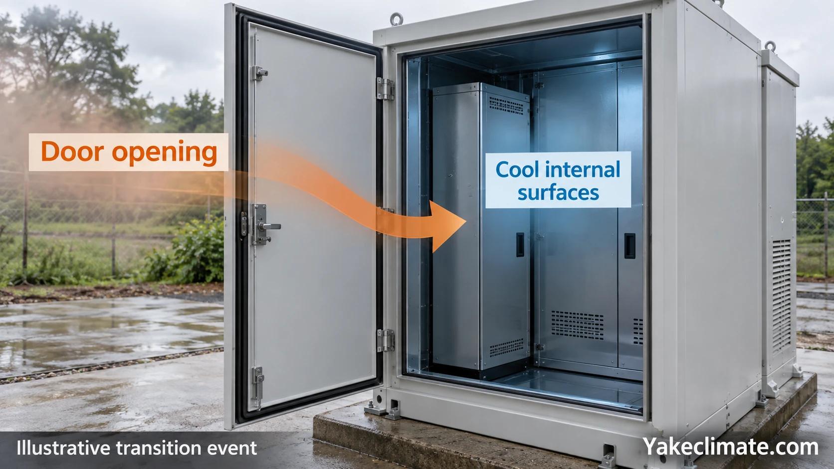
Door opening
A door event can introduce outdoor air while internal surfaces remain cool. Record outdoor conditions, door-open duration, local airflow, and recovery after closure.
Cooling shutdown
When cooling stops, air and surfaces warm at different rates. Moisture may enter or redistribute while a high-thermal-mass component remains cold.
Restart
Cold supply air or a cooled component can appear before the enclosure moisture condition has recovered. Control sequencing matters.
Day-night ambient change
The enclosure boundary can cool while internal heat load falls. A surface that was safe during the day may become controlling at night.
Maintenance and service
Open panels, personnel, tools, wet materials, or temporary ventilation can create a different moisture load and airflow path.
IEC 60068-2-30 specifies an environmental test procedure combining high humidity and cyclic temperature change that generally produces condensation on a specimen surface (IEC 60068-2-30:2025). Its scope supports the need to consider cycles. It does not prescribe a BESS commissioning test, prove compliance, or set a field control target.
Convert the physics into a control specification
A reviewable specification should define the condition, evidence, response, and responsibility.
1. Name the protected surfaces or zones
State what the control objective covers. Include the representative cold points and how they were selected.
2. Define the air measurement
State the quantity, location, range, calibration status, logging interval, response requirement, and uncertainty.
3. Define the surface measurement
State the sensor location, response requirement, and how it represents the actual critical surface.
4. Define the event profile
Include normal steady operation, shutdown, restart, door opening, maintenance, ambient change, and any project-specific disturbance that can change the comparison.
5. Assign the control action
Possible actions include source correction, sealing, drainage, insulation, heating, cooling-sequence changes, air-distribution changes, or dehumidification. Each action addresses a different mechanism.
6. Assign responsibility
The process, electrical, thermal, fire-protection, controls, validation, enclosure, and equipment roles should be explicit. The system designer owns the integrated control condition and project target. The equipment manufacturer can confirm equipment performance and interfaces only for the defined duty and condition.
Do not use one number as a substitute for the control plan
A universal dew-point target or fixed temperature buffer is not defensible without the enclosure, environment, measurement uncertainty, event profile, and consequence framework.
A lower air dew point may reduce condensation risk, but it does not repair a drain, eliminate a water leak, warm a thermal bridge, correct short-circuited airflow, or validate a sensor. It can also create an equipment duty that has not been checked against the actual operating condition.
Information needed for equipment evaluation
Prepare:
- enclosure drawings, materials, insulation, and penetrations;
- indoor and outdoor environmental profiles;
- critical surface locations and measured or modeled temperatures;
- air measurement locations, instruments, calibration, and uncertainty;
- door, shutdown, restart, maintenance, and weather-event profiles;
- air volume, leakage or outside-air information, and airflow paths;
- current cooling, heating, drainage, and control sequence;
- project-defined environmental objective and recovery requirement;
- electrical, installation, drainage, communications, maintenance, and service constraints.
These inputs allow the remaining moisture duty and equipment interfaces to be reviewed. They do not transfer the integrated enclosure, electrical, fire, or controls design to the dehumidifier manufacturer.
For event diagnosis in an AC-equipped container, see Why BESS Containers Can Condense Even with Air Conditioning. For the wider application context, see Industrial Dehumidification for Energy Storage.
FAQ
Frequently asked questions
Is dew point more useful than RH for enclosure condensation control?
At a stated pressure and unchanged moisture content, dew point is less temperature-dependent than RH. Dew point changes when moisture content or pressure changes. Condensation assessment still requires the local surface temperature and nearby air condition.
Where should the dew-point sensor be installed?
There is no universal location. It should represent the air associated with the protected zone or surface and be accessible for validation and maintenance. Multiple points may be required when the enclosure is non-uniform.
Can one room sensor protect every internal cabinet?
Not automatically. Internal cabinets can have different airflow, heat load, leakage, and surface temperatures. Their relationship to the main sensor must be demonstrated.
Is there a universal control allowance between surface temperature and dew point?
No. The project owner must set the control condition after considering risk, measurement uncertainty, response, and event behavior. This article does not publish a default value.
When should dehumidification be considered?
When a defined moisture-removal duty remains after ingress, drainage, cold-surface, and airflow issues are addressed, and when the equipment can be evaluated at the project condition.
Control the local condition through the real event
Battery enclosure condensation control is a local, measured, event-based task. Identify the relevant cold surface, measure the nearby air, account for uncertainty, and verify transitions before defining equipment duty or control response.
Yakeclimate designs and manufactures industrial dehumidification equipment for complex climate applications. To review equipment fit, share the enclosure conditions, measurement basis, and event profile.


